


INTRODUCTION
Accurate recording of physical data is a critical task that dentists perform daily. The restorative workflow begins with preparing the area to be restored. This area, and the surrounding teeth and tissue, must be precisely captured. The definitive restorations are then designed and created.
In the analog world, the data is captured with physical impressions, bite records, and face-bows. Models are fabricated from the impressions. Traditionally, the design phase involves manually waxing the desired final contours on mounted stone models, then manufacturing the final restorative product.
However, data can also be captured digitally with an intraoral scanner, resulting in a digital file. While digital technology captures data in a different way, it is still the same data used in the analog workflow.
Many software programs are available to create a computer-assisted design (CAD), such as CEREC (Dentsply Sirona), 3Shape, Simplant (Dentsply Sirona), and exocad. CAD programs were originally intended for use in the dental laboratory, with the expectation that the CAD design and manufacturing elements would be outsourced to the laboratory and not done in the dental office. Many of these programs are complex and have a steep learning curve to use them correctly.
However, 53% of dentists now use intraoral scanners (IOS). IOS digitally capture 3D images of intraoral hard and soft tissue.1 To accommodate the increasing number of dentists using IOS in their practices, the hardware, software, and workflows have evolved to give dentists a multitude of options to best adapt the technology to their practice needs.
The design software can now be purchased in segments, so dentists can start with only the CAD portions that apply to their immediate needs. Live courses geared toward the dental team to learn this technology are also available. Once one segment has been mastered, additional modules can be added, allowing the dental team to increase its range of design and fabrication options.
When the CAD portion of the workflow is done in the dental office, the dentist has more control of the functional and aesthetic outcomes. Dentists also appreciate the flexibility of designing and manufacturing on their own time schedules. Patients can view lifelike mock-ups of proposed treatments, which often increases their acceptance of definitive treatment plans.
This article will outline in detail the steps necessary to digitally take a case from data collection through design using in-house CAD software. It will also demonstrate the steps necessary to perform a chairside evaluation of the digital mock-up and how to make any needed corrections to enhance the prototypes and final restorations.
CASE REPORT
A 27-year-old male patient was referred to the office by his orthodontist. Prior to surgery, he had been diagnosed with moderate obstructive sleep apnea and a bimaxillary retrusive malocclusion. The orthodontist aligned the arches with fixed appliances prior to orthognathic surgery. The patient presented postoperatively after a maxillary and mandibular surgical advancement, a LeFort 1 osteotomy on the maxilla, and a bilateral sagittal-split osteotomy on the mandible.
Treatment goals established by the surgeon and orthodontist included enhancing both the facial aesthetics and improving the airway space (Figure 1).
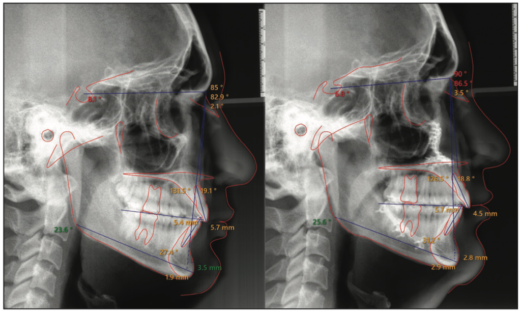
Figure 1. Initial and final traced lateral cephalometric radiographs. Note the improved upper and lower jaw relationships relative to the cranial base.
The patient first presented to the office with orthodontic brackets in place. The orthodontist requested guidance to determine the ideal overbite-overjet relationship to accommodate future restorative materials and to obtain an ideal functional pathway. The patient desired to change the anterior tooth length, shape, and color. Photographs were taken (Figure 2).
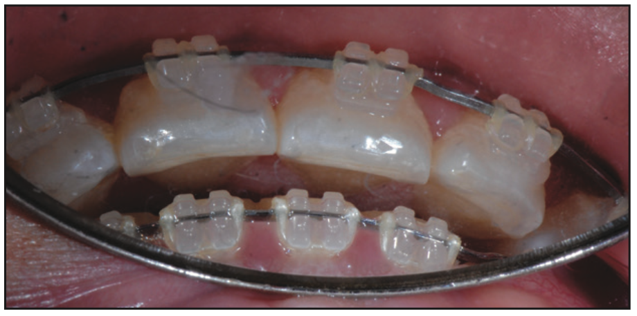
Figure 2. The overbite-overjet relationship was evaluated to ensure room for future restorative materials.
A direct composite mock-up was performed chairside to test the aesthetics and function of the proposed increased incisor length. Composite was added to the incisal edge of tooth No. 8. The patient was seated upright, and articulating paper was placed between the arches as he simulated his chewing pattern. There was less than 1 mm of clearance during chewing. The orthodontist was therefore instructed to tilt the incisal edge of the upper centrals 1 mm facially and intrude the lower incisors by 1 mm. The final goal after porcelain augmentation incisally would be to have 15% to 20% horizontal overlap and 1 mm of space between each arch in the chewing pattern.
After debanding, the patient returned and a comprehensive exam, a full-mouth series of radiographs, a periodontal evaluation, diagnostic photos, and digital scans (iTero [Align Technology]) were completed.
The patient’s medical history was noncontributory. His initial goal was to attain a “natural, beautiful appearance.” He did not like his existing short, square, yellow-speckled front teeth; misshapen lateral incisors; worn flat edges of the anterior teeth; and lack of buccal corridor fullness. He had no history of whitening.
Analysis
Maximum lip dynamics occur when a person engages both the zygomatic major and the orbicularis oculi muscles.2 During a full E smile, he displayed all gingival tissue on his maxillary teeth in the aesthetic zone3 (Figure 3). Dentofacial, the patient was high-risk with a poor prognosis for a successful aesthetic outcome because everything that needed to be restored was visible. He had a high gingival scallop and inflamed gingival tissue. He presented with a crooked smile that he reported having had his entire life. The right vermillion border was more apical than the left side when he smiled. His dental midline was concentric with his facial midline. His mandibular incisors were worn and in need of whitening and composite augmentation at the edges.
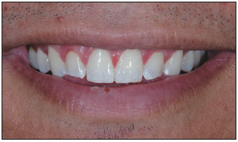
Figure 3. Preoperative view. Note the misshapen, short, square, yellow teeth with worn edges and the crooked smile.
Upon evaluation from a frontal perspective, 10 maxillary teeth were in the aesthetic zone. He liked the positioning of the second bicuspids and felt the fullness in that area was acceptable. The patient did not believe that including the second bicuspids in the restorative treatment plan would significantly improve the aesthetic outcome, so he elected to have only teeth Nos. 5 to 12 restored with minimally invasive veneer restorations.
In-House Digital Design
Dental software design programs include options to use many different materials. A simplified workflow is outlined below that demonstrates designing provisional prototype restorations.
1. Load the software (exocad) on a PC and fill in the patient data.
a. Choose one tooth (in this example, it was tooth No. 5) to be incorporated into the design.
b. For a provisional where the tooth has not been prepped, choose “anatomic pontic.” The design program will add wax to the top of that tooth.
c. The “waxup” option is for a tooth that has been prepped. When this option is selected, the design program will place wax over the prepped tooth. “Waxup” is intended to be used in the lab, and for our simplified purposes, we chose “anatomic pontic.”
Select the material category, which is “3D print,” followed by adding any additional teeth to be incorporated in the design (in this case, teeth Nos. 5 to 12) (Figure 4). The teeth in the opposing arch will automatically appear as antagonists, facilitating functional and occlusion verification.
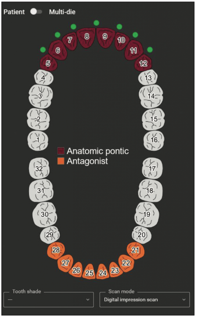
Figure 4. The start of the design process.
2. Choose “digital impression scan” for the scan mode, then save the prescription and proceed to the design.
3. The STL file is then exported from the scanner website in PLY format (which is colored to mimic the visuals of the arches) one arch at a time and oriented in occlusion.
4. The STL files are loaded. Rotating these files allows visualization of the overjet spacing available for restoration design (Figure 5).
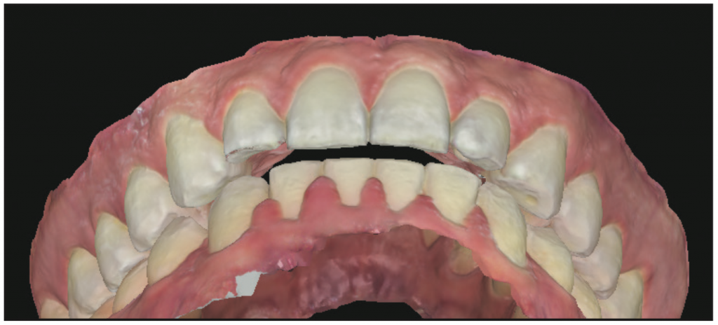
Figure 5. The STL files were rotated to evaluate the available restorative space.
5. Hover over the upper left, and slide the bars to change the translucency and allow the designer to show or hide an arch or tooth. This allows the removal of an arch or the selection of every tooth or every other tooth for designing purposes. Two modes, wizard and expert, can be used to design. Wizard mode gives a sequential series of prompts, while expert mode allows the operator to move between the prompts in whatever order desired. Hovering over an icon turns it orange, and text pops up explaining that prompt. Scan data orientation is adjusted and synced.
6. Choose the tooth form from the program library (Figure 6).
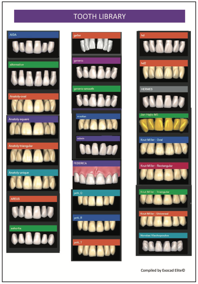
Figure 6. Tooth-library options.
a. To move the teeth as one unit, select “chain mode” and place the tooth models over the occlusal surfaces from the distal contact of tooth No. 5 to the distal contact of tooth No. 12 (Figure 7).
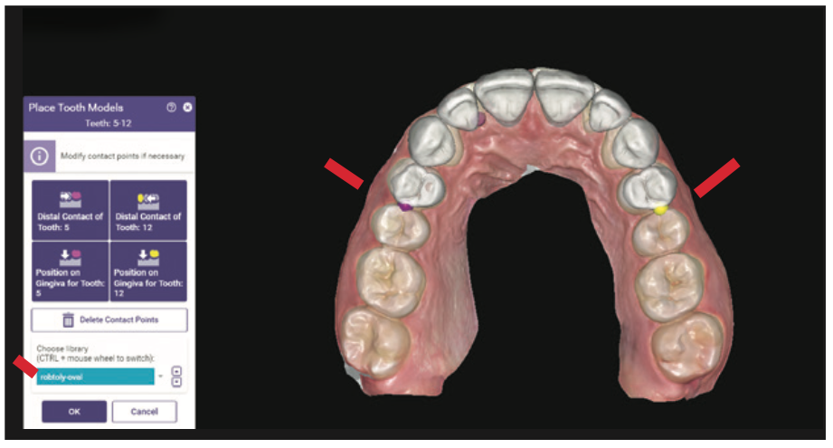
Figure 7. Teeth were moved as one unit in “chain mode.”
b. Clicking on the green dots will change the color to red and lock that tooth in place. Future movement can occur in the chain without the red-dot teeth moving (Figure 8).
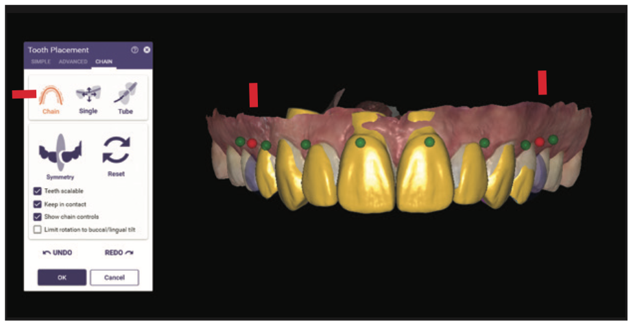
Figure 8. The teeth marked with the red dots could not be moved, while those marked in green could be moved.
c. Choose “tooth placement, single move” to allow movement of one tooth at a time, which does not allow for movement of the other teeth. To increase the fullness of the buccal corridor, the facial surfaces of the cuspids and bicuspids were intentionally designed with over-contoured facial and buccal surfaces (Figure 9). The proposed incisal edges were intentionally designed longer and with more closed and square incisal embrasures than the anticipated final, approved contours.
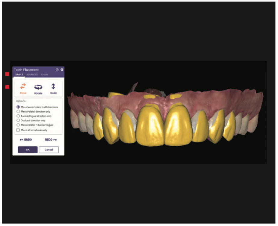
Figure 9. Note the overcontouring of the facial surfaces to increase buccal corridor fullness.
7. The “tooth placement, advanced slide bar, anterior” function changes the edges from oval embrasures to flat embrasures (Figure 10). This gives the patient the ability to actually see how the smile would look if the veneers were made too long, too square, and/or too full. The dentist can then adjust contours, flatten the facials, and shorten and round the incisal edges during the provisional phase. This allows feedback from the patient until the patient approves of the smile design in the prototypes. Since the patient helps design the shape, form, and length, he or she takes more ownership of the aesthetic result. In this case, since the tooth forms were placed fuller and facially, a dehiscence was created at the neck, or cervical, of the central incisors.
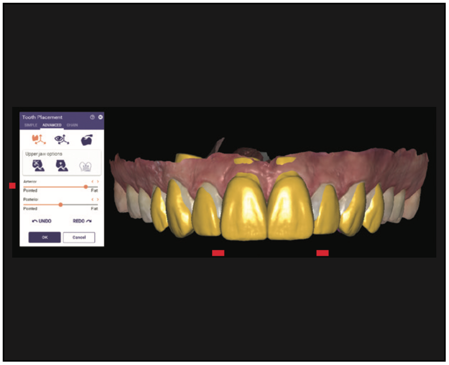
Figure 10. The “advanced changes” slide bar was used to flatten the incisal edges. Note the closed square incisal embrasures.
8. The “free-forming tool” was used to maintain the shape and form of the central incisors and move the necks. The design is rotated into a sagittal intraoral view. This tool allows the locking of the incisal edge and movement of individual tooth-form parts (ie, moving the cervical design inside of the tooth). This tool also allows editing of individual tooth parts, cusps, and ridges or the entire tooth (Figure 11).
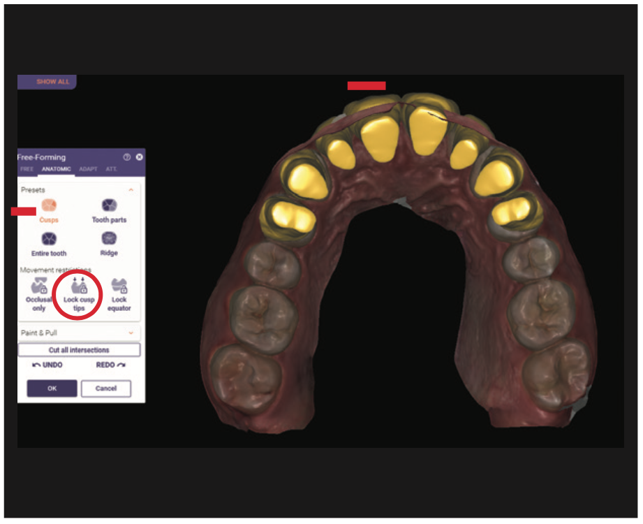
Figure 11. The sagittal intraoral view, free-forming locks the incisal edge and moves the neck of the prototype. Note that tooth No. 8 had been adjusted and No. 9 had not.
9. When the frontal perspective adjustments are complete, the occlusal is evaluated by looking at excess lingual material over the cingulum, which appears yellow (Figure 12). This must be removed for veneer design. The portions of the restoration that are in occlusion show in pink. These tooth parts are removed by using “free-forming anatomic tooth parts” and pulling tooth parts away from the natural-tooth lingual contours.
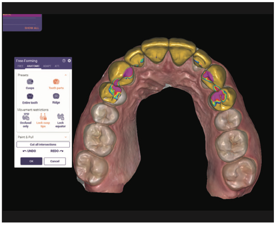
Figure 12. The areas in pink were occlusal interferences to be removed. Note the yellow contour on the lingual that needed be removed for veneers.
10. The “free-forming free tool” is used for a final cleanup, allowing the designer to add or remove virtual wax. This tool acts like a virtual waxing knife. Wax is added by clicking and removed by hitting shift while clicking. Fine-tuning and shaping is accomplished by clicking “smooth/flatten” and holding shift to flatten or control for smoothing (Figure 13). The antagonist mandibular arch is brought into the scene, and the occlusion, overbite, and overjet are evaluated. Hovering over the upper left and sliding the bars will change the translucency and allow you to view the proposed design over the preoperative dentition (Figure 14).
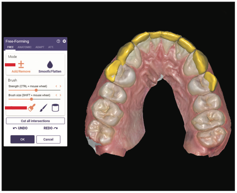
Figure 13. The “free-forming free tool” was used for final cleanup, as it allows the operator to add or remove virtual wax.
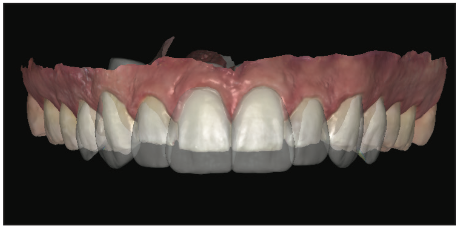
Figure 14. The proposed design was superimposed over the pre-op dentition by changing the translucency.
11. Export the final approved design as an STL file and send it to the 3D printer for fabrication of a maxillary model. Then fabricate a siltech provisional matrix (Virtual XD [Ivoclar]).
Preparation Appointment
Local anesthetic was administered on the maxillary arch. The provisional matrix functioned as a preparation guide to ensure appropriate, but minimal, reduction. The guide was loaded with bis-acrylic composite (Luxatemp Ultra B1 [DMG America]) and seated over the maxillary arch.
The resulting prototypes were previewed. The length was shortened, and the middle thirds were flattened, then approved. Depth cut diamonds (Brasseler RWMIN .3/.5/.7 828.31.030 [Brasseler USA]) were placed across the facial gingival and middle third and established the facial reduction (Figure 15).
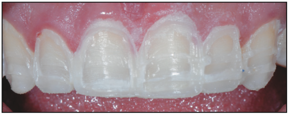
Figure 15. Depth cuts made into the approved prototypes ensured minimal reduction.
Next, 2 mm were removed from the previously approved incisal edge length, and since we lengthened the centrals 3.5 mm, no incisal reduction of the tooth preps was necessary.4,5 A lingual chamfer design was chosen to enhance the resistance form of the preparation and to provide increased enamel surface for increased bond strength.6 The preparations were refined, and the gingiva was retracted.
Records can be taken using a digital, analog, or hybrid workflow. A face-bow of the prepared teeth (Panadent), MIP bites (O-Bite [DMG America]), PVS impressions (Honigum [DMG America]), and photo documentation were taken and sent to the lab. Provisionals were fabricated with bis-acrylic composite (Luxatemp B1 [DMG America]) by loading the provisional matrix and then placing the matrix over the prepared teeth. The provisionals were luted with a combination of spot etching and bonding with Duo-Link veneer cement (BISCO) in the center of the prep and TempoCem ID (DMG America) at the periphery. In order to achieve high-strength, definitive, aesthetic restorations, IPS e.max Press (Ivoclar) Ingot HTBL 2 was selected as the material of choice.7,8
One week later, the patient returned for an evaluation of the provisionals’ shape, form, color, and function. He had initially asked for natural-looking veneers that were undetectable when compared to his existing mandibular teeth. This would have required color gradation and a combination of these A and B shades in the final porcelain. After wearing the provisionals in a B1 shade, he now wanted the new restorations to be slightly lighter and brighter than his existing lower teeth. He chose BL3 as the main body color. The outline forms of the contralateral teeth were contoured to be slightly different to allow the patient to view the different shapes and decide which he preferred. He chose symmetry, which is an exact duplication from left to right for his central incisors and accepted harmony, which was defined as a recurring theme, for his laterals and canines.
He gave written approval of the proposed shapes and shades for the definitive restorations. Final shade photos were taken in the same plane as the provisionals (Figure 16). Photo orientation and head position are critical to aesthetic digital design. The retracted, full-face photo is taken with the patient wearing Kois Facial Reference Glasses, which are designed to simplify capturing the correct head posture in photos (Figure 17). These additional records allow the ceramist flexibility in fabrication of the restorations in either the analog or the digital realm.
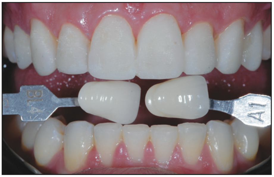
Figure 16. Provisionals with shade tabs communicated the desired color and shape to the ceramist.
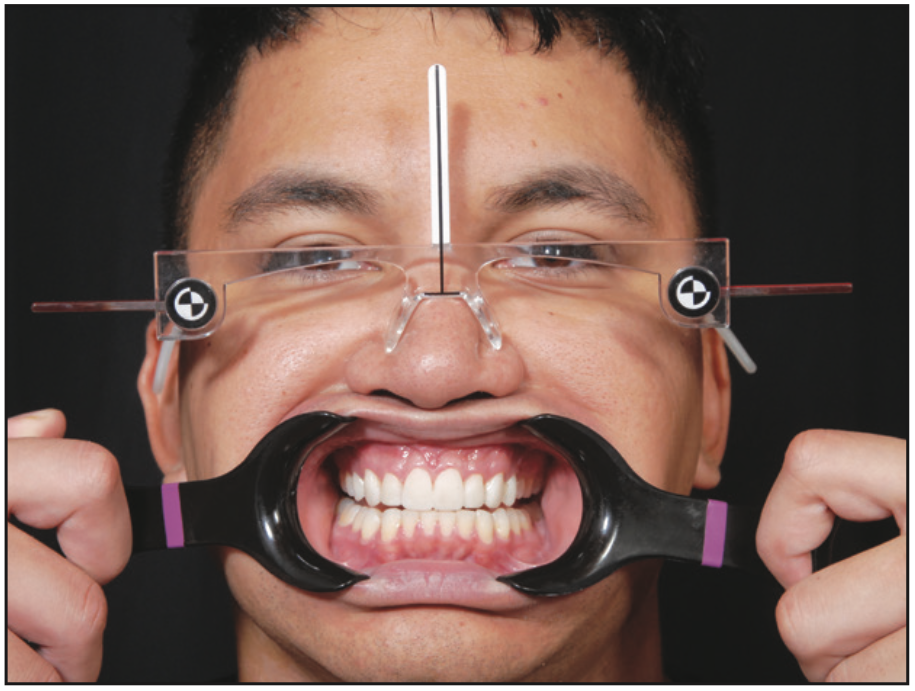
Figure 17. Kois Facial Reference Glasses captured the correct head position.
A digital scan of the approved provisionals is taken, sent to the lab to print, and is used as the master guide to design the porcelain restorations (Figure 18).
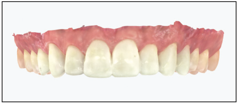
Figure 18. A scan of the approved provisionals was sent to the lab to print.
Using photographs, the ceramist and dentist communicate virtually throughout the porcelain fabrication stages to ensure and verify that the aesthetic goals of the patient are met (Figures 19 and 20).
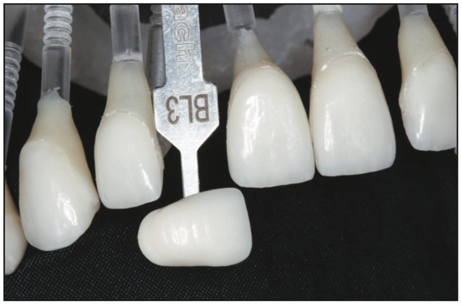
Figure 19. The color and translucency of the IPS e.max restorations (Ivoclar) were verified virtually between the dentist and ceramist.
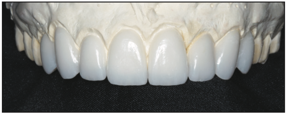
Figure 20. IPS e.max lithium disilicate restorations on the model verified shape characterization surface texture and incisal embrasures.
At the delivery appointment, the patient was anesthetized, the provisionals were removed, and the preparations were cleaned with pumice on a rubber cup (Figure 21).
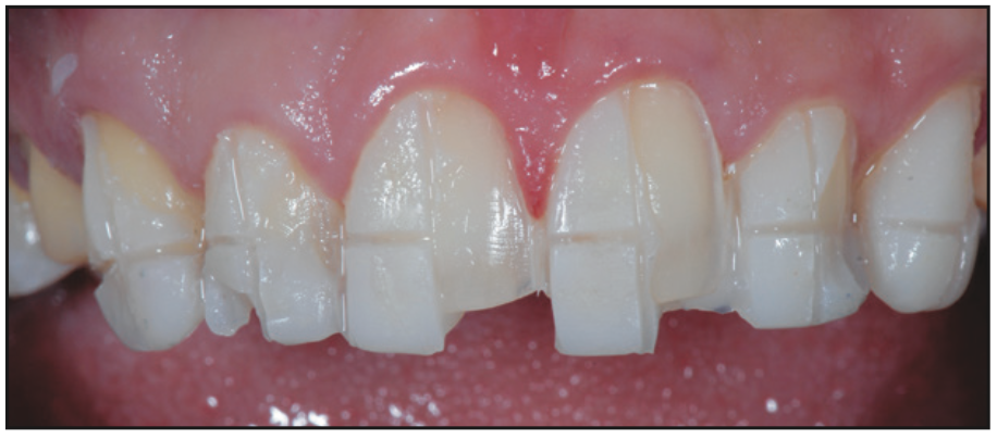
Figure 21. Sectioning, then removal of provisionals.
The porcelain restorations were placed intraorally for aesthetic evaluation, (shape, color, and length), and written approval by the patient was obtained. The ceramics were HF-etched in the laboratory, and after try-in, the ceramics were cleaned by applying 37% phosphoric acid to the internal surface of the porcelain for 20 seconds, followed by rinsing with water. Next, the ceramics were primed by using silane (Bis-Silane, a 2-part silane coupling agent [BISCO]), allowing it to remain on the internal surface for one minute, followed by air drying. This step adds an organic molecule to the porcelain, which increases the adhesion by adding a chemical bond between the porcelain and resin cements.
The tooth surfaces were then prepared for cementation, and the teeth were isolated (OptraGate [Ivoclar] and MicroEtcher [Zest Dental Solutions]).9 Evaluation of the remaining tooth structure revealed a thick ring of enamel. A selective-etch technique was used, applying etch only to the remaining enamel of the tooth structure and preventing the etching solution from touching the exposed dentin in the middle of the tooth. This facilitates greater mechanical retention of the veneers. A high-viscosity etch containing benzalkonium chloride (BAC) was placed on the enamel for 15 seconds, then rinsed with water (Select HV Etch [BISCO]) (Figure 22).10
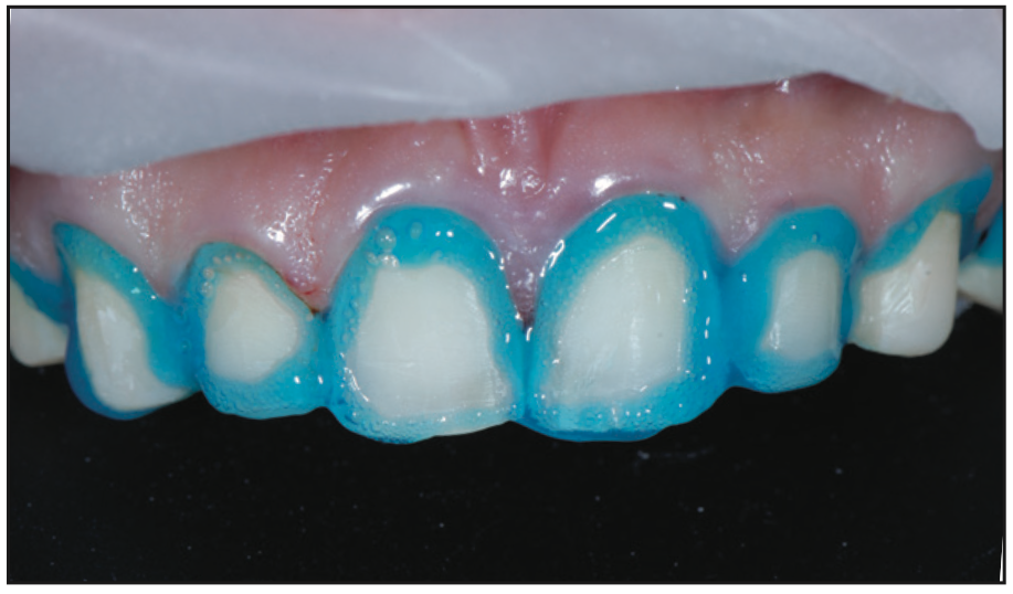
Figure 22. A selective benzalkonium chloride etch technique avoided acid on the middle of the tooth where dentin was exposed in the preparation.
The high viscosity of the etchant minimizes slumping of the etch and allows the placement to be confined to the enamel. The BAC assists in inactivating the matrix metalloproteinases (MMPs). MMPs are believed to degrade the hybrid layer over time. An ethanol-based universal bonding agent (Adhese Universal [Ivoclar]) was applied to the teeth, scrubbed for 20 seconds, and air-dried for 10 seconds. Once the bonded surfaces were confirmed to be glossy and immobile, the preparations were light-cured for 10 seconds. The veneers were then luted into place with a light-cured resin cement (Variolink Esthetic LC [Ivoclar]).
After cement removal, the restorations were equilibrated. The patient closed in maximum intercuspal position until all posterior teeth displayed bilateral, simultaneous forces. The functional occlusion was evaluated with the patient sitting up in the chair and chewing on thick (22-µm) articulating paper, which simulates the chewing envelope, activating the closing muscles. A digital scan of the maxillary reconstruction was taken, Essix retainers were fabricated, and the patient was instructed to wear the Essix retainers indefinitely to maintain the achieved results (Figures 23 and 24).
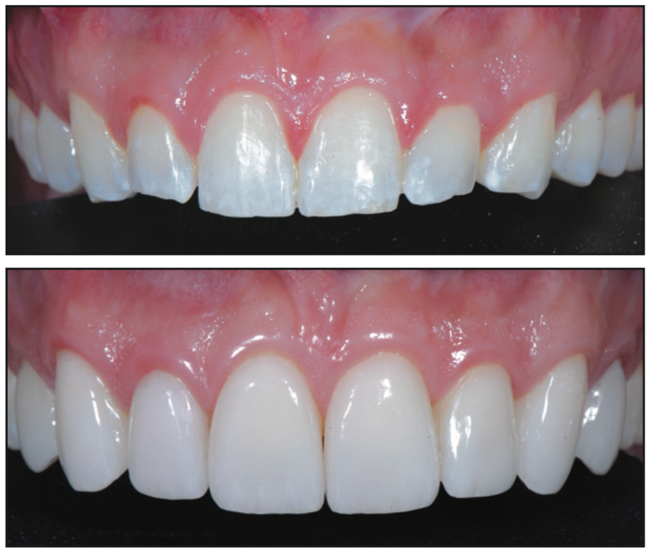
Figure 23. Preoperative and postoperative close-up 1:1 view.
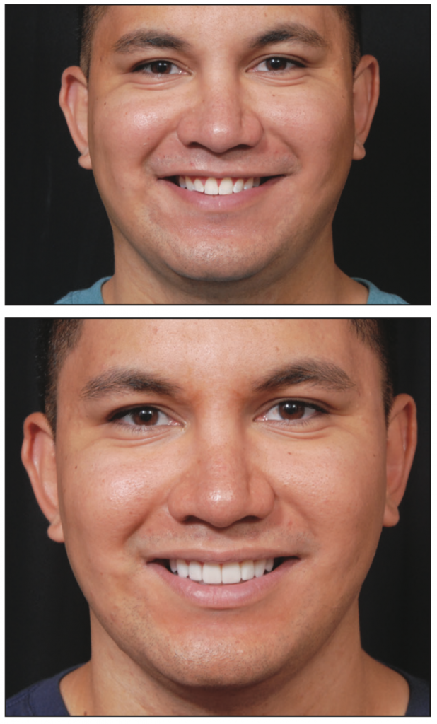
Figure 24. Pre- and post-op smile.
SUMMARY
This case demonstrates a state-of-the-art, real-time digital workflow with the CAD done in the dental office. This process allows the prototype design to be linked to the definitive porcelain restorations while also allowing the dentist flexibility in designing and controlling the functional and aesthetic outcomes. The final outcome is predictable, and the process provides patient involvement in the aesthetic decision-making process, which improves patient satisfaction. While there is a learning curve in mastering the software, virtual and in-person educational opportunities are available. There has never been a better time to incorporate in-office CAD design. The advantages of improved restorative outcomes and patient satisfaction make it worth the effort to learn to use these tools.
ACKNOWLEDGMENTS
The author wishes to thank orthodontists Dr. Mark Steig and Dr. John Wachtel, surgeon Dr. Michael Golding, laboratory ceramist and artist Sandy Cook of Microdental NW, and Dr. Jean Martin for editing expertise. The concepts in this article are based on the teachings of Dr. Diana Tadros and the Kois Center.
REFERENCES
1. Revilla-Leon M, Frazier K, da Costa JB, et al; Council on Scientific Affairs. Intraoral scanners: an American Dental Association clinical evaluators panel survey. J Am Dent Assoc. 2021;152(8):669–70.e2. doi:10.1016/j.adaj.2021.05.018
2. Duchenne de Boulogne GB. The Mechanism of Human Facial Expression. Cambridge University Press; 1990.
3. Hochman MN, Chu SJ, Tarnow DP. Maxillary anterior papilla display during smiling: a clinical study of the interdental smile line. Int J Periodontics Restorative Dent. 2012;32(4):375–83.
4. Gürel G. The Science and Art of Porcelain Laminate Veneers. Quintessence Publishing; 2003.
5. Magne P, Belser UC. Novel porcelain laminate preparation approach driven by a diagnostic mock-up. J Esthet Restor Dent. 2004;16(1):7–18. doi:10.1111/j.1708-8240.2004.tb00444.x
6. Chaiyabutr Y, Phillips KM, Ma PS, et al. Comparison of load-fatigue testing of ceramic veneers with two different preparation designs. Int J Prosthodont. 2009;22(6):573–5.
7. Anusavice KJ. Standardizing failure, success, and survival decisions in clinical studies of ceramic and metal-ceramic fixed dental prostheses. Dent Mater. 2012;28(1):102–11. doi:10.1016/j.dental.2011.09.012
8. Bühler-Zemp P, Völkel T, Fischer K. Scientific Documentation IPS e.max Press. Ivoclar Vivadent AG; 2011.
9. Onisor I, Bouillaguet S, Krejci I. Influence of different surface treatments on marginal adaptation in enamel and dentin. J Adhes Dent. 2007;9(3):297-303.
10. Tezvergil-Mutluay A, Mutluay MM, Gu LS, et al. The anti-MMP activity of benzalkonium chloride. J Dent. 2011;39(1):57-64. doi:10.1016/j.jdent.2010.10.003
ABOUT THE AUTHOR
Dr. Bassett practices comprehensive restorative and aesthetic dentistry in Scottsdale, Ariz. She is an Accredited Fellow of the American Academy of Cosmetic Dentistry and served as its president from 2015 to 2016. Dr. Bassett is a Kois clinical instructor, a member of the Academy of Fixed Prosthodontics, a Diplomate of the American Board of Aesthetic Dentistry, a Fellow in the AGD, an associate member of the American Academy of Esthetic Dentistry, and a member of the Catapult Education Speakers’ Bureau. She can be reached via email at drmouthy@aol.com or via the website drbassett.com.
Disclosure: Dr. Bassett reports no disclosures.


